
Forward
This page describes the steps necessary to remove and replace the input transformers found in a Presonus model M80 eight channel microphone preamplifier. Since the circuitry for the two channel model MP20 is for the most part identical to the M80, much of the information presented here should be useful and relevant for that model too.
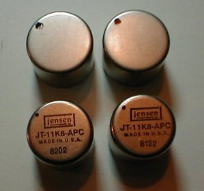
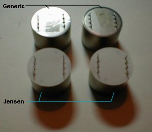
The original transformer used in both the M80 and MP20 was made by Jensen Transformers and was model JT-11K8-APC ( from here on referred to simply as a 'Jensen' ) The transformer currently used is of unknown manufacture and is found in units that were made around the beginning of the year 2000 to date. ( from here on referred to simply as a 'generic' )
Both transformers are enclosed in cylindrical metal packaging that is approximately 1" tall and 1" in diameter and have eight pins on the bottom in two parallel rows of four pins each. A pin 1 indicator dot is printed on the top to ensure correct installation. The Jensen's are also clearly marked on the top with the Jensen logo, part number, country of manufacture and manufacturing lot number. The generic's have no markings other than the pin 1 indicator dot and are slightly bigger in diameter than the Jensen's. Also the construction of the bottom is slightly different between the two with the Jensen's having a more complete method of case insulation.
|
|
It is important to realize that even though the steps to swap transformers are simple and few, this is not a project for beginners or those without specialized soldering tools and skills. Desoldering a component from a double sided and hole plated through circuit board, especially one that you can only access from one side like these transformers, is not an easy task without the proper tools and is a job best left to an experienced tech. This page is here only as an aid for those who are going to attempt the transformer replacement and a fair degree of mechanical aptitude, soldering technique, electronics repair experience and patience is assumed.
At the bottom of this page are three links that will take you to the various stages of my comparison experience. The first is 'The Overview' and will explain the circumstances that led to changing transformers in the first place. The second link is 'The Listening Tests' and will allow you to make up your own mind which transformer you prefer on a variety of sound sources. The third is a short discussion of what my conclusions and opinions are about the tests.
I sincerely hope that you will find this site interesting, if not useful, and I'm open to any comments or suggestions you might be willing to share.
Best of luck!
Tools
| Tool | Notes |
| cross-slot screw drivers | for removing and attaching chassis top and XLR screws |
| 12mm nut driver | for for removing and attaching ¼" jack 'nuts' |
| soft rubber mallet |
for loosening XLR connectors if needed |
| desoldering iron |
for removing transformers from circuit board |
| desoldering braid | for removing transformers from circuit board |
| soldering iron | for attaching transformer to circuit board |
| electronics grade solder | for attaching transformer to circuit board |
| defluxing aids | for removing excess flux from circuit board after soldering |
| misc. | needle nose pliers, magnifying glass, small bright flashlight |
Instructions
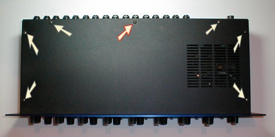
| 1 | Remove the seven screws that hold the top cover of the chassis on. Note that the center rear screw ( marked with red highlight ) may be a little shorter than the other screws and if so make sure you replace this screw in the same hole when putting the M80 back together. This is to make sure the screw doesn't come in contact with the circuit board beneath it. |
|
| 2 | Note the row of eight transformers and if they are Jensen's or generic's. Since this unit is a newer model with generic transformers, two of them will be replaced this Jensen's. | |
| 3 | Inside the M80 remove the power cable from the circuit board by pulling up on the white connector. | 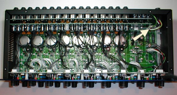 |
| 4 |
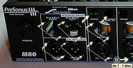
Remove the 'nut' from each of the ¼" phone jacks. The word 'nut' is in quotes because they really are not the type of threaded nuts you might expect. Even though they look like black plastic nuts they are more of a bayonet locking device and only need a very gentile counter clockwise 1/8 rotation to release them. Use caution. Remove the two screws from each XLR input and output connector. It is important to note that the input and output XLR connectors use different sized screws so keep separated. |
 |
| 5 | Remove the four front panel screws. | |
| 6 | Next slide the entire front panel and circuit boards assembly towards the front of the case and remove. This is easier said than done. The XLR connectors fit very tight in the chassis, surprisingly so, and it may require the use of a soft rubber mallet to loosen them. Be patient and gentile as you evenly tap back and forth on the XLR connectors until they loosen. The bottom row of input jacks seemed to be the tightest. DO NOT tap on the ¼" jacks! | |
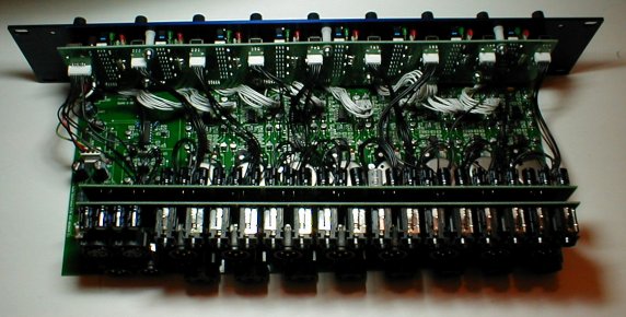
| 7 | This is what the assembly looks like from the rear after being removed from the chassis. |
|
| 8 | This is what the empty chassis looks like. Note that the power connector remains. | |
| 9 | Locate the transformers to be removed. In this instance the transformers for channels 1 and 2 are to be removed. | 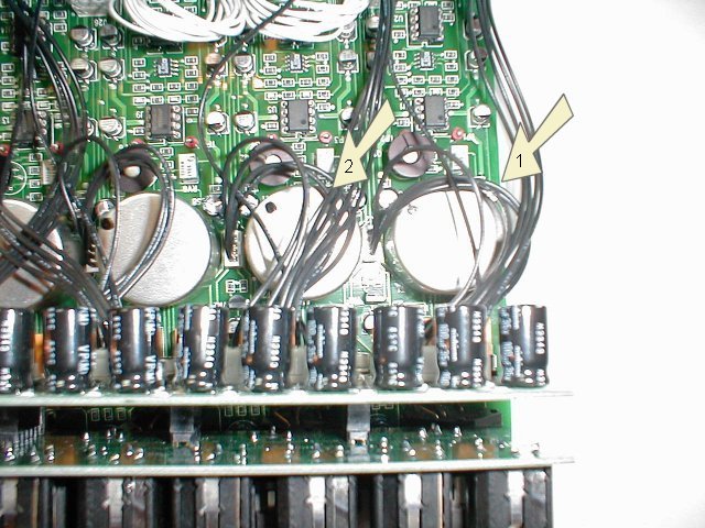 |
| 10 | Turn the assembly over and locate the correct transformer solder points for the selected channels. There will be eight pins per transformer and they will be grouped in two parallel rows of four pins each. Using a desoldering iron remove the solder from the selected solder points. Desoldering braid may also be useful. Once all the solder is removed if the transformer cannot be pulled away from the circuit board it may be necessary to carefully grab each pin with needle nose pliers and gently wiggle it until it breaks free. | 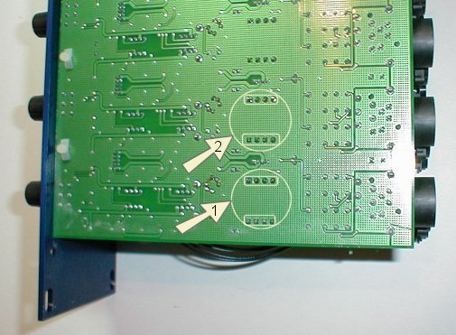 |
| 11 | This is how the bottom of the circuit board looks with the transformers for channels 1 and 2 removed. | 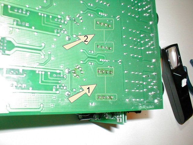 |
| 12 | This is how the top of the circuit board looks with the transformers for channels 1 and 2 removed. | 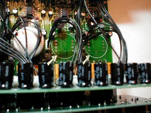 |
| 13 | Put the new transformers in position using the pin 1 indicator dot to make sure they are placed correctly. | 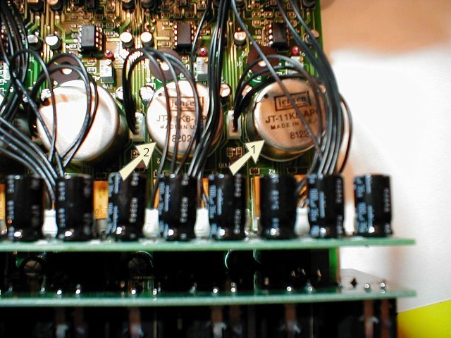 |
| 14 | Reassemble the M80 in the reverse order that you took it apart in. Slide the circuit boards and front panel assembly back into the chassis. The upper two smaller circuit boards that contain the XLR output jacks and ¼" insert jacks can be carefully folded back to make it easier to line up the XLR input jacks first. | 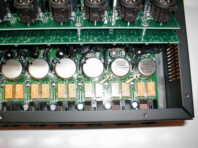 |
| 15 | If it is difficult to get the bottom row of XLR connectors back into their holes get them at least close enough so that one of the screws can just be started, then progressively and gradually add more screws until they are all in and use small turns to evenly pull the assembly into the chassis. ( Make sure you are using the correct sized screw for each connector! ) Place the upper rows of jacks back into their holes and then replace and tighten all back panel screws. Finally carefully replace the ¼" jack 'nuts'. | |
| 16 | Attach the front panel to the chassis by replacing the four screws. | |
| 17 | Make sure to reconnect the power cable to the circuit board by pushing down on the white connector inside the M80. | 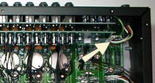 |
| 18 |
Attach the top cover of the chassis using the seven screws, making sure that the short screw is in the center rear hole, ( marked with red highlight ), if necessary to make sure the screw doesn't come in contact with the circuit board beneath it. This concludes the transformer swap. Plug in the M80 and check for correct functionality. Once you have verified that everything went well you will be ready to conduct listening tests and / or begin recording. |
 |
| An explanation of the circumstances that led to changing transformers and conducting listening tests. |
| Audio samples in MP3 and WAV formats for comparing the sound of the two transformers. |
| My conclusions and opinions about the testing. |
| What Other People Think |
| Tests, modifications and opinions of others. |